Compressor Connection System
23 June 2022, Thu
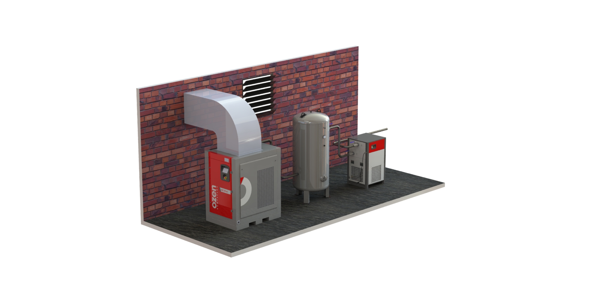
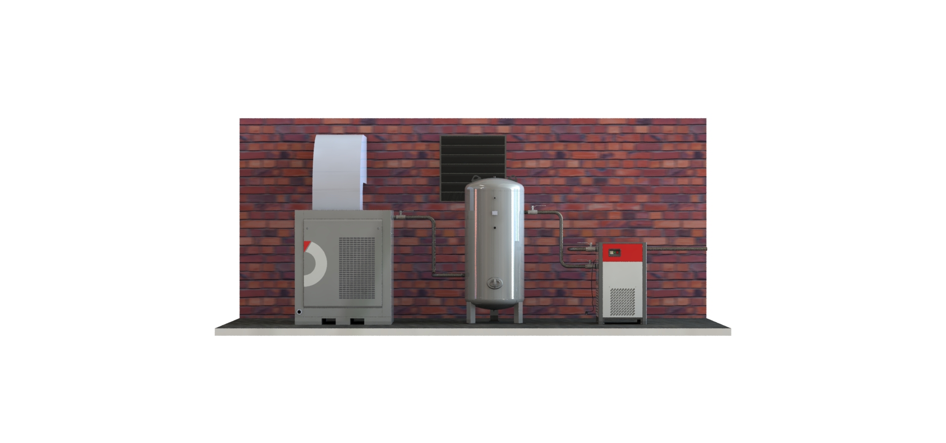
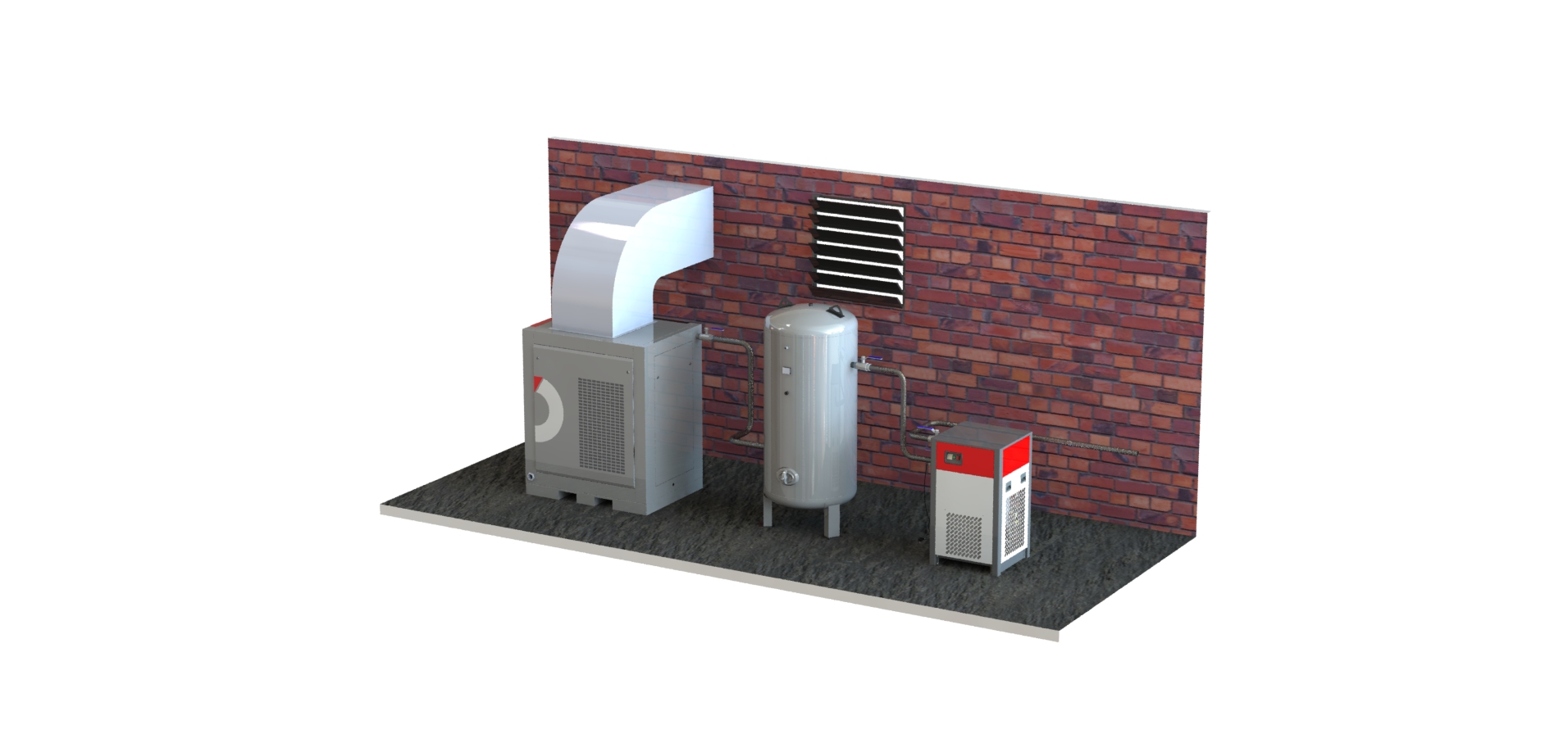
The most important factor in the compressor connection system is the installation of the main pipe network. The air coming from the compressor with pressure moves through all the pipes, passes through the entire installation, and ensures an effective pressure in the desired place. More than one factor plays a role in the transmission of the air coming from the compressor to the final point at the desired pressure. The first of these factors is the calculation of the pipe diameter. Along with the pipe diameter, the scheme of the installation is also essential. Furthermore, all factors such as the filter, dryer and condensate discharge line, etc. in the compressor installation affect the effective operation of the compressor connection system.
Calculation of Compressor Installation (Pipe Diameter)
Correctly adjusting the pipe diameter in the compressor installation directly affects the air pressure. If the pipe diameter is smaller or larger than the required, it causes pressure loss. It is important to calculate the pipe diameter correctly, particularly for preventing the pressure loss in the separated pipelines. There are multiple factors in determining the pipe diameter. These factors are as follows:
- Main pipe network diameter
- Diameter of pipes in the separated pipeline
- Highest airflow rate
- The amount of friction inside the pipe
- Additions to be made in the future periods
- Air flow rate used
- Pipeline length
- The amount of moisture inside the air used
- The material of the pipe to be used (resistance to flow rate)
The diameter can be determined according to the pipe material by using the tables indicating the flow loss of the pipe materials. The most important point in all compressor connection systems is to keep the pressure loss at the lowest level.
The general formula used to determine the flow rate of air through the pipe is as follows:
V = 1273*Q / (P+1)*D2
The general formula used to calculate the minimum pipe diameter for the main piping is as follows:
D = ((212*Q / (P+1))½
The general formula used to calculate the maximum flow rate that can pass through the main piping is as follows:
Q = (P+1)*D2 / 85
The components for the formulas are as follows:
V = airflow rate (meters/second)
Q = airflow rate (litres/second)
P = air pressure (bar)
D = calibre (millimetres)
Why Ring Piping?
Ring piping is formed by configuring the pipeline in a circle shape. The ring pipeline is not in a full round shape geometrically. The reason why it is called a circle is that it can ensure the circulation over the entire line without interrupting the airflow. The ring pipe network provides many advantages particularly in areas where many points of air usage are required. Being used with two separate air inlets in general, the ring compressor connection system allows partial interruption of the airflow without interrupting the valves where the airflow rate can be adjusted when desired or the use.
In the ring piping system, when the air velocity on the main line is kept at the lowest possible level, it offers possibility for the construction of a safer and more wear-resistant pipeline. In case of any malfunction or maintenance requirement, the area to be intervened can be easily bypassed. On the other hand, the airflow continues and helps to prevent loss of usage and workforce. In addition to these, undesired wastes such as moisture and oil accumulated in the pipe can be discharged by placing drainage points in appropriate areas on the ring pipeline, and a dryer can be placed on the main line in order to keep the air at the lowest level for better keeping the air in circulation.
The following items should be applied in order to get the best efficiency from the ring piping line:
- The pipeline should be built higher than the ground for easy drainage.
- The main pipeline should wrap the entire area of use.
- The bends of the pipes should consist of large curves instead of sudden bends.
- The main line should be sloped and reverse sloped at appropriate intervals.
- There should be drainage areas at the lowest points of the slope.